How to build a vertical wire antenna: step-by-step

 If you need a simple, effective DX antenna for portable or home station use, please check out this basic “Rybakov” vertical  antenna from Walt (K4OGO).

This project is one of several antenna ideas contained in Walt’s book “Salty Walt’s Portable Antenna Handbook.”

Walt take us step-by-step through the design, building, testing, and use of this basic antenna.  The antenna is easy to deploy and can be made from locally available materials.

If you can’t see the video, please insert this title URL into your browser search box:  https://www.youtube.com/watch?v=Yu2tNFAEixQ

Thanks for joining us today.

Russ (KH6JRM).

Here are some comments from Walt (K4OGO).

5/8 wave vertical antenna for 10 meters

 Do you want to improve the DX capability of your antenna on the 10 meter Amateur Radio Band?  You can get a low take off angle and nearly 3dB gain over a 1/4 wave vertical if you use a 5/8 wavelength antenna.

In this video, Walt (K4OGO) erects a 5/8 wavelength vertical antenna for 10 meters and shows how it can boost your DX performance.

Most material for this antenna project can be found locally or through online vendors.

If you can’t see the video, please insert this title URL into your browser search box:  https://www.youtube.com/watch?v=MJJoUMZ9-bM

Thanks for joining us today.

Russ (KH6JRM/AL0HA).

Here are some comments from Walt (K4OGO):

Building and using a 5/8 wave vertical wire antenna for the 10 meter ham band. #hamradio #portablehamradio #hamradioantenna

DIY 10-40 Meters Tactical Delta Loop HF Antenna

 If you’re looking for a simple, effective HF antenna for portable or home station use, please consider this delta loop design from Jack (W3CT).

The delta loop antenna is a full-wavelength, triangular HF antenna that is “quiet” and exhibits a bit of gain over a conventional dipole antenna.

In this video, Jack shows us how to build, test, and use a delta loop antenna in a variety of configurations.

If you can’t see the video, please insert this title URL into your browser search box:  https://www.youtube.com/watch?v=q47OZwc8bs8

Thanks for joining us today.

Russ (KH6JRM/AL0HA).

Here are some comments from Jack (W3CT):

This video shows how I built a Delta Loop Ham Radio Antenna. I really enjoy building different types of antennas for POTA and home use. Grab a notebook and follow along with building my first Delta Loop Ham Radio Antenna.

#DIYHamAntennas #BuildingHamRadioAntennas #CW #MorseCode #HamRadio #HomemadeHamAntennas #Homemadehamantennas #DeltaLoopAntenna #DeltaLoopHamRadioAntenna #9:1Unun #Buildinghamradioantennas #cheaphamantennas #lowcosthfantennas #buildyourownhamantenna #speakerwifehamantennas


The Doublet-Best Multi-Band Antenna?

 According to Tim (K5OHY), if you want a HF antennas that is “simple, versatile, and (produces) great results”, build a multiband doublet antenna.

In this video, Tim explores the pros and cons of the “classic” doublet antenna.

After taking us through the antenna build, Tim deploys the doublet for a QRP activation with excellent results.

If you can’t see the video, please insert this title URL into your browser search box:  https://www.youtube.com/watch?v=eSS1dw3e5Oc

Thanks for joining us today.

Russ (KH6JRM/AL0HA).

Here are some comments from Tim (K5OHY):

I cover the advantages of a multiband doublet, show some modeling, and then deploy it for a QRP activation.

STL files used

Doublet Center : https://www.thingiverse.com/thing:703…

Doublet Center: https://www.thingiverse.com/thing:437…

Ladder-line spacer (25 mm): https://www.thingiverse.com/thing:703…

Doublet info:

Cebik, W4RNL — All-Band Doublet (PDF): https://webclass.org/k5ijb/antennas/1…

Cebik — “Suppose I Could Have Only One Wire Antenna” (44′ Doublet): http://www.antentop.org/w4rnl.001/ale…

De-Mystifying Dipoles and Doublets: http://gnarc.org/wp-content/uploads/T…

KV5R ladder line: https://kv5r.com/ham-radio/ladder-line/

Timestamps

00:00 Intro
03:30 Advantages of a Doublet
10:30 Modeling
14:05 Deploying
17:56 Activation
24:11 Activation Results
25:38 RBN Spots by Band
28:32 Conclusion

Ham Radio Antenna-What actually works

 Thanks to Callum (M0MCX) for this nice collection of antenna ideas that “work extremely well for a small garden or backyard.”

Most of these simple, proven antenna projects can be built using locally available materials.  These antennas are easily deployed and “blend in” with your surroundings.

If you can’t see the video, please insert this title URL into your browser search box: 

https://www.youtube.com/watch?v=BUDCfzXpvuk.

Thanks for joining us today.

Russ (KH6JRM/AL0HA).

Here are a few comments from Callum (M0MCX):

HOA and UK Planning laws: You don’t need towers, stealth tricks, or neighbour disputes to enjoy HF. In this video I walk through simple, proven antenna ideas that work extremely well from a small back garden or backyard, whether you’re in the UK or the USA. We’ll look at why verticals shine on the higher bands, why low dipoles and loops are brilliant on 40 m and 80 m, and how combining transmit and receive antennas can transform your station.

This isn’t clickbait. It isn’t stealth. It’s about scale, shape, take-off angle, and being considerate.

With a bit of wire, a balun, and some common sense, you can work the world without upsetting anyone – and have a lot of fun doing it.

IDEAS:
   • Maximizing Your Signal in a Small Space: A…  
   • Receive Antennas – This is my Loop On Grou…  
   • Full Build Deploy & Test – Multiband 40m S…  

Enjoy your radio, Callum.

Ask

DXCommander

Inverted V HF DX Antenna-From a Back Yard

 One of the easiest HF DX antennas you can build is the “classic” inverted V dipole.  The antenna needs only one support and can be erected on a fairly small urban lot.

In this video, Peter Waters (G3OJV) discusses the pros and cons of this versatile HF antenna.  Multiband capability is reached by using a balanced feedline and a sturdy antenna “tuner.”

You can use this antenna for both portable and home station use.

If you can’t see the video, please insert this title URL into your browser search box:  https://www.youtube.com/watch?v=lvgDyzY58EU

Thanks for joining us today.

Russ (KH6JRM/AL0HA).

Here are some comments from Peter (G3OJV):

I built a military TEFV Antenna for HF Ops

 If you need a broadband, multiband HF antenna with excellent “directivity” then the military-based Terminated End Fed Vee Antenna” is for you.

In this video, Walt shows how to design, build, test, and use this fascinating HF antenna.  This antenna is easy to deploy and is perfect for portable operations.

If you can’t see the video, please insert this title URL into your browser search box:  https://www.youtube.com/watch?v=CCmi84GMNJQ

Thanks for joining us today.

Russ (KH6JRM/AL0HA).

Here are some comments from Walt (K4OGO):

I built a US Military TEFV antenna to spec and worked the HF bands #hamradio #portablehamradio #hamradioantenna

Link to Palomar Engineers maker of the 12:1 balun and 600 ohm termination resistor:

https://palomar-engineers.com

Dual Band J-Pole Build

 If you need a “rainy day” antenna project, then this dual band (2m/70cm) J-Pole antenna is for you.

In this video, Mike (M0MSN) shows us how to make a roll-up J-Pole VHF/UHF antenna from commonly available parts.  The antenna is lightweight, sturdy, and exhibits a low takeoff angle.

This antenna is suitable for both portable and home station operations.

Thanks for joining us today.

Russ (KH6JRM/AL0HA).

Here are some comments from Mike (M0MSN):

HAM RADIO: Easy SlimJim / J-Pole Dual band Antenna Build for 2m/70cm, Thanks to a book I purchased many moons ago, I have found the perfect way to pass a rainy day. make a 2M / 70cm Slim Jim or J-Pole. Not just the standard J-Pole but one that uses a decoupling stub so that you get the maximum power on both bands……….

You need:

1.5M of 300 Ohm ladder line
15cm /6 inches of RG176 or RG316 coax

and that’s it, Bobs your uncle.

Many thanks
Mike – M0MSN
To get notified of the next upload .click that bell and subscribe..

Short Ham Antennas for HF with linear loading

“Short Ham Antennas for HF with linear loading.”

Views expressed in this Amateur/Ham Radio antenna project are those of Claude Jollet (VE2DPE).

Content and Source provided by Claude Jollet (VE2DPE).

https://www.hamradiosecrets.com/short-ham-antennas.html

Please check URL or scroll down to read your selections.  Thanks for joining us today.

Russ Roberts (KH6JRM/AL0HA).

https://arrlnewshawaii.blogspot.com.

https://simplehamradioantennas.blogspot.com.

Short Ham Antennas
For HF
With Linear Loading

by Claude Jollet – VE2DPE

You may have heard that short ham antennas are not as efficient, nor as effective as a “full length” half-wave dipole, regardless of the configuration chosen.

Good news! I describe in this article the only exception I know of … that actually works!

To be honest, even if effective, the antenna described below will tune somewhat sharply (narrower 2:1 SWR bandwidth) than full half wave dipole.

When you don’t have the space, you have to accept a few compromises.

However, this “shortened” antenna will not disappoint you! John, OZ3PAX built one for the 17 meter band. Read his comment here.

I believe the details of this technique were first published a while back by John Stanford, NN0F.

Linear Loaded
Short Ham Antennas

For many ham radio operators, it is not feasible to put up a full length dipole on HF.

But, a linearly loaded dipole just might fit in your available space!

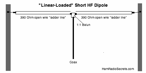
A linearly loaded dipole, as illustrated below…

  • … is about 30-35% shorter than a “classic half-wave dipole” at the same frequency of resonance!
  • … has a radiation resistance around 35 Ohms. (You will need an impedance matching tuner at the other end of the coax!)
  • … just as effective as a “full length” half-wave dipole! :-)
Linear-loaded short ham antennas for HF.

Note that it “looks” like a folded dipole, but the top part is open! You should add a ceramic end-insulator in the opening, to add mechanical strength. (The insulator is omitted in the drawing to make the opening obvious;-).

A More Efficient Version

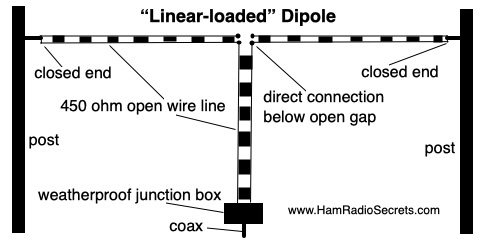
Ladder line linear-loaded dipole fed by ladder-line.

A more efficient version would be to feed a linear-loaded dipole short ham antenna directly with 450 ohm ladder line or 300 ohm twinlead.

As I work mostly QRP, I need to minimize RF losses as much as possible. Ladder line, and to a certain extent twinlead, are much less lossy transmission lines than coax.

I only use RG-8X coax to enter the radio room and to connect to a tuner. The coax is connected directly to the ladder line outside, just before it enters the shack. The connection is protected inside a weatherproof box.

You must use a RF choke on the coax, outside, before it enters the shack. To that end, you can use a coax choke, as described on this other page of this website.

Or you can use ferrite chokes that clip on the coax. (You can tell that you need more RF chokes when your tuner has trouble stabilizing on a setting when you transmit.)

As always, I recommend an “L” network tuner for maximum efficiency.

Here is what Tim G5TM (alias for 2EOTWG) had to say about this antenna:

“The 40m linear loaded dipole worked very well so I took away the coax and fed it with 300 ohm ribbon line. Wow! (it now) tunes 10-80 … never thought it would tune 80 but it does and it works very well … Thanks for sharing the idea and your advice.” (Tim was using a IC-7300 with its internal automatic tuner.)

Shorter Dimensions!

Here are “ballpark” dimensions for a linearly loaded dipole for each ham radio band. These dimensions are intentionally slightly long! You will have to obtain the final dimensions experimentally, on site, by “pruning” to resonance.

Have you forgotten the technique to prune a dipole to resonance? Refresh your memory on the page about the ham radio dipole!

Linearly-Loaded Dipole
Approximate Dimensions

10M (28.5 MHz)  3.5 m. (11.5 ft.)
12M (24.9 MHz) 4.0 m. (13.2 ft.)
15M (21.1 MHz) 4.73 m. (15.5 ft.)
17M (18.1 MHz) 5.51 m. (18.1 ft.)
20M (14.1 MHz) 7.08 m. (23.2 ft.)
30M (10.1 MHz) 9.89 m. (32.44 ft.)
40M (7.1 MHz) 14.06 m. (46.14 ft.)
80M (3.6 MHz) 27.74 m. (91.0 ft.)
160M (1.85 MHz)53.97 m. (177.08 ft.)

The lengths given in the chart above are those of the full overall length (total breadth) of the bottom half of the linear-loaded dipole. The dimensions include the width between the balun connections.

The gap in the top section can be a few inches wide at HF (ex. the length of a normal end insulator).

Construction Of Linear Loaded
Short Ham Antennas

I use commonly available 390 Ohm “ladder line” with #14 stranded, copper-clad conductors. It is sturdy and lasts for years. 450 Ohm ladder line will work just as well.

For the central “attachment” I use two LadderLoc center insulators, head-to-head. (I used a BNC to dual-pole center connector for an indoor version of a linear-loaded 10 meter dipole).

The extremities of the ladder line linearly loaded dipole are connected together.

After pruning the ends to get resonance at the desired frequency, I recommend soldering them together to ensure a long-lasting electrical bond. If not soldered, copper oxidization will eventually render the connections resistive and unreliable.

The top gap can be 3-4 inches wide. It’s not critical for use on HF.

I recommend 3/16 in. Mil Spec Dacron® rope to tie the ends to tall supports such as trees.

Bonus Configurations!

Linear-loaded short ham antennas do not have to be limited to horizontal installations!

You can save even more space by installing them as “slopers”, inverted “V”s and inverted “U”s.

I describe these configurations in detail on space-saving ham radio HF antennas.

How Does Linear Loading Work?

An antenna system is composed of the antenna, its transmission line (and a balun or UNUN if one is used) and the antenna tuner when one is used.

Linear loading is a technique to obtain a shorter, yet still resonant and efficient antenna on the frequency for which it is designed.

Let’s take the example of a linear-loaded dipole for 40 meters.

The 40-meter linear-loaded dipole is essentially a single band antenna, but it can also be efficient on 21 MHz, its third harmonic.

Of course, it can also be coaxed into serving on other bands with an antenna tuner… and the tuner will fool you into thinking that you can, just because you can bring the SWR of the entire antenna system down!

The tuner serves to hide any mismatch between the antenna system’s impedance and your transceiver’s input/output impedance. The tuner transforms, within itself, the mismatched impedance of the antenna system to the 50 ohms impedance of the transceiver. The tuner is an impedance transformer. It does NOT render the antenna resonant at the other end of the transmission line.

Just be aware that the linear-loaded dipole will be much (much) less efficient on other frequency bands than its fundamental frequency of resonance which, in this case, is in the 40-meter band and its third harmonic in the 15-meter band.

What is the purpose of linear loading short ham antennas?

To explain how the linear-loaded dipole antenna works, let’s recall the theory of resonant circuits and apply it to an antenna.

When we take a length of wire to form a coil, the mutual coupling between the turns of the coil increases the inductance and the proximity of the coil turns form a capacitor contributing the necessary capacitance to yield a frequency of resonance.

A dipole antenna at resonance is a resonant circuit. It is the result of the combination of inductance (L) and capacitance (C).

Therefore, think of a dipole antenna as a pair of coils that have been stretched out to form straight wires, one on each side of the feed point (hence the name ‘dipole’).

Now imagine that you wind a portion of wire on each side of the dipole’s feed point to form a helical coil terminated by a remaining straight length of wire. You end up with a coil-loaded dipole with a reduced overall “wingspan”. The coils introduce lumped inductances in the antenna, replacing part of the stretched-out antenna wire. That’s the most popular way of obtaining short ham antennas.

Now, in the case of the linear-loaded dipole, we simulate a large one-turn coil on each side of the feedpoint by folding back each half of the dipole antenna on itself.

The folded back portion of wire interacts with the antenna wire above (or below, depending on how it is installed). The frequency of resonance of the dipole antenna is the result of the self-coupling of the two wires on each side of the antenna feedpoint.

In other words, each side of the antenna becomes part of a resonant circuit with inductance (length of wire) and capacitance (proximity of wires to each other forming a capacitor).

Linear loading allows preserving the resonance of a shortened dipole for the same given frequency of a regular size dipole.

Can the linear-loading technique be applied to a multi-band fan dipole? Read on and find out…

If you really want to go deeper into the theory of short antennas, see this reference.

Have fun! See you on HF.
73 de VE2DPE


Claude Jollet VE2DPE

Claude Jollet, VE2DPE, has been a licensed ham since 1973 and shares decades of HF wire antenna and propagation experience at HamRadioSecrets.com. He has published many books on HF wire antennas. Readers can find him on Amazon, Youtube, QRZ and UNEQ.

Found this page useful? Please pay it forward. Here’s how…

Would you prefer to share this page with others by linking to it?

  1. Click on the HTML link code below.
  2. Copy and paste it, adding a note of your own, into your blog, a Web page, forums, a blog comment, your Facebook account, or anywhere that someone would find this page valuable.

73 de VE2DPE
Claude Jollet
104-30 avenue des Berges,
Notre-Dame-des-Prairies, Québec, Canada J6E 1M9

QTH Locator: FN36gb


How to build a 40 meter loaded coil

 Here’s an excellent “rainy day” project for radio amateurs.

In this video, Simon (VA7BIX) shows us how to build a sturdy, inexpensive 40 meter band load coil from locally available materials.  

Simon takes us step-by-step through the design, construction, testing, and use of this useful antenna accessory.  Make one for your next portable operation.  The coil is lightweight and will fit comfortably in your emergency “go kit.”

If you can’t see the video, please insert this title URL into your browser search box:  https://www.youtube.com/watch?v=FCm2b_y3iIo

Thanks for joining us today.

Russ (KH6JRM/AL0HA).

Here are some comments from Simon (VA7BIX):

What if you could build a real 40-meter loaded coil antenna for under $5… in about 15 minutes? 😂

In this video, we build one of the simplest, cheapest and most effective DIY ham radio antenna projects on the HamJazz channel using basic hardware store parts and a little creativity.

This build is:
✔️ cheap
✔️ portable
✔️ beginner friendly
✔️ quick to build
✔️ ridiculously fun 😄

Perfect for:
📻 portable operations
📻 experimenting outdoors
📻 emergency setups
📻 learning antenna basics
📻 junk-box antenna projects

You’ll learn:
⚡ how to build the loaded coil
⚡ materials needed
⚡ wire measurements
⚡ assembly tips
⚡ simple tuning concepts

This video is now part of the growing HamJazz “Rubbish Antenna Series” ecosystem where we turn simple materials into real-world antenna experiments 😄

🔥 WATCH NEXT – Rubbish Antenna Series Playlist:
   • RUBBISH ANTENNA SERIES (RAS) — Turn Junk I…  

🎬 More HamJazz Videos:

📻 $5 DIY 5-Band Antenna
   • $5 DIY Ham Radio Antenna – 5 Bands, No Tun…  

📻 Tape Measure Antenna Hack
   • This Tape Measure Hack Will Blow Your Mind…  

📻 Extension Cord 10M Hack
   • This Extension Cord Antenna Should NOT Wor…  

📻 MoonCool Ham Radio Trike
   • Ham Radio Tricycle?! Is It Even a Thing? -…  

🛒 HamJazz Amazon Store:
https://amazon.com/shop/hamjazz

❤️ Support the channel:
  / hamjazz  

WOOOHOOOO mates 😄

⏱️ Chapters:
00:00 Introduction
00:45 Shopping List / Materials Needed
01:01 Measurements
02:15 Drilling Caps
02:48 Wire Length / 16AWG
03:12 Feed Wire Through PVC – 13 Turns
03:45 Solder Ring Terminals
04:25 Final Assembly
05:51 Weatherproofing & Final Touches
06:37 What’s Coming Next
07:02 Thanks For Watching Mates